Cold Plate Channel Spacing Using the Biot Number
6/10/20264 min read
Why Channel Spacing Makes or Breaks Your Cold Plate — and How to Get It Right
The overall efficiency of any cooling system is determined by its weakest link—the segment with the highest thermal resistance in the chain from heat source to heat sink. When designing a thermal management system, identifying and optimizing this bottleneck is everything. ( Check out our post on thermal resistances. Here we'll solely concentrate on cold plates)
In many applications—battery packs, power electronics, laser systems or industrial machinery—cold plates with internal cooling channels are the go-to solution. These are suited for moderate heat flux densities where the thermal load is spread over a reasonably large area. (When heat flux densities become extreme, as in semiconductor devices, channel dimensions must shrink to the sub-millimeter range — a technique known as microchannel cooling. At that scale, the physics and design rules change significantly, making it a topic worthy of its own discussion.)
For cold plates, once you've selected your coolant, flow rate, and plate material, one geometric parameter dominates the thermal performance: channel spacing. Get it wrong, and the conduction path between channels becomes the bottleneck of your entire cooling system. Get it right, and you achieve uniform temperatures with minimal effort.
So how do you determine the right spacing? The answer lies in the Biot number—a dimensionless ratio that tells you whether your channel spacing is thermally appropriate for your specific combination of material and coolant. In this post, we'll walk through what exactly the Biot number tells us and how to put that knowledge into action.
Understanding the Cooling Plate Challange
When designing a cold plate, engineers must balance several competing objectives:
Dissipate the required heat amount
Achieve uniform surface temperature gradient
Keep pressure drop within acceptable limits (pumping power)
Reduce manufacturing costs and material usage
Ensure structural integrity
Mitigate corrosion risk by sufficient wall thickness
Enabling mounting of components to the cold plate
Channel spacing directly influences all these factors. The spacing determines how far heat must conduct laterally through the plate material to reach a cooling channel. If this conduction path is too long, the thermal resistance of the plate itself becomes the bottleneck—and no amount of coolant flow will fix that.
The Role of the Biot Number
The Biot number ($Bi$ ) is a dimensionless parameter that compares the relative magnitudes of internal heat conduction resistance to convection resistance. This seemingly simple ratio is the key to understanding whether your channel spacing is appropriate.
The Biot number is defined as:
$$Bi=\frac{(h\times L_c)}{k}$$
Where:
$h$ = convection coefficient of the cooling fluid (W/m²·K) calculated with the Glieanciksi formula for the given channel and flow conditions
$L_C$ = characteristic length (m) (typically the half-distance between channels)
$k$ = thermal conductivity of the plate material (W/m·K)
What Does Biot Number Tell Us?
The Biot number reveals whether temperature gradients are more significant inside the solid or at its surface:
$Bi << 0.1$ (Much less than 0.1): Internal temperature gradients are negligible; the entire plate is nearly isothermal. The cooling is limited by convection at the fluid boundary. In transient contex means lumped mass modelling represents the system fairly good.
$0 < Bi < 1$: The range in which cold plates should be
$Bi > 1$ (Much greater than 1.0): Internal temperature gradients dominate; the cooling is limited by the plate's ability to conduct heat to the channels. This suggests channel spacing is too large.
Optimal Channel Spacing Using Biot Number. Example.
For cooling plate design, the target range for the Biot number is typically 0.1 to 1.0. Hence the spacing §S§ between channels using the Biot could be written as:
$$S = 2 \times L_c = \frac{(2\times Bi \times k)}{h} $$
Let's go through one concrete example that asumes the following cooling plate and cooling channel conditions:
Cold Plate L = 300mm, W = 200mm:
k = 380 W/mK, Copper
Cooling Channel:
Ø = 5mm
l = 300mm
Re = 11039
$h$ = 10793 W/m²K (Gnielinski correlation)
$$S = 2 \times L_c = \frac{(2\times Bi \times 380 \times 1000)}{10793} $$
In Table 1 some channel spacing are beeing presented as a function of different Biot values.
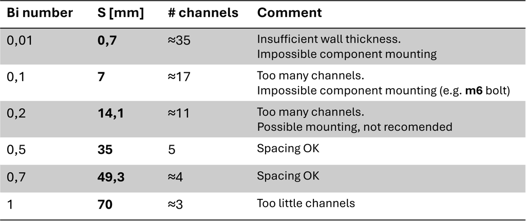
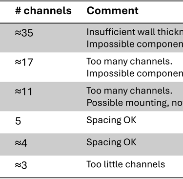
Table 1: Channel spacinng and number of channels depending ont different Bi values.
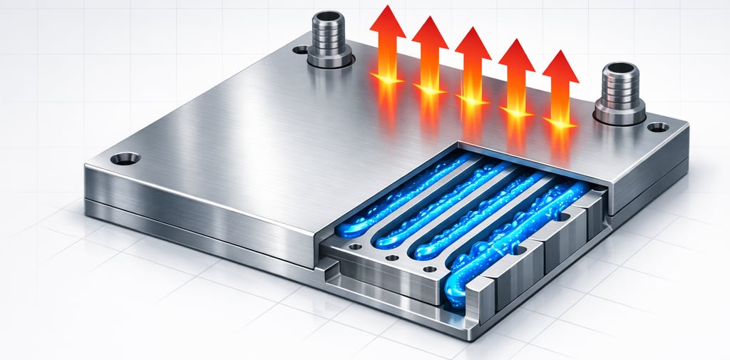
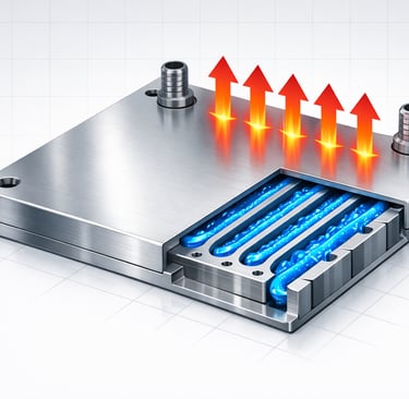
From Table 1 and Image 1 we can conclude that probably 4 or 5 channels are going to be a good trade-off to ensure the best cooling performance, sufficient wall thickness and the ability to use fasteners to mount the actual components that need to be cooled.
Verdict.
The Biot number is powerful tool for hand calculations and fast determining of cooling plate channel spacing. By understanding the balance between internal conduction and external convection it is possible to take informed design decisions that optimize performance, cost, and manufacturability. The key takeaway- target a Biot number between 0.2 and 0.7 for most applications, use this to calculate initial channel spacing, then validate with detailed analysis (CFD / FEM) and testing.


Image 1: Cold Plate with 3 / 4 / 5 Cooling Channels
Consulting / Simulation / Analysis
Expertise in thermal management and optimization solutions.
chillwave@analytics.com
+4917657864718
© 2025. All rights reserved.