Counteracting the Path of Least Resistance: A Practical Guide to Flow Balancing
2/14/20263 min read
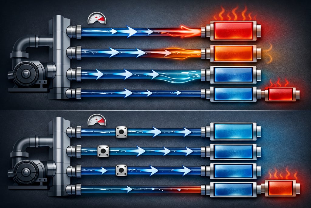
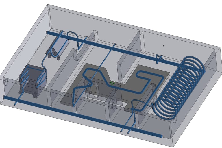
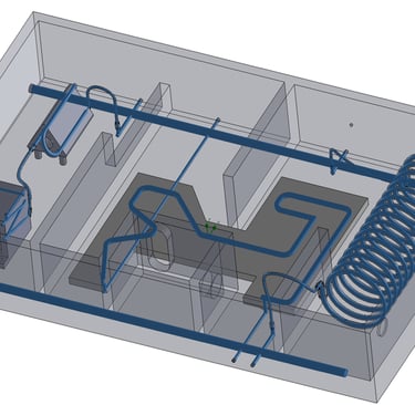
Image 1: Water Cooled Module and Cooling Water Domain (in Blue)
First, a baseline simulation is performed to capture a snapshot of the module’s initial hydraulic behavior, including the flow distribution among the parallel branches and the corresponding pressure drops. This establishes the reference state and clearly identifies over- and under-supplied cooling paths. (Table 1 - IS)
Using this baseline, the pressure drop at the desired target flow rate is then estimated for each branch using the equation given below. The branch exhibiting the highest pressure drop defines the limiting hydraulic condition of the system (Table 1 - Target). Based on this constraint, the available pressure budget for additional flow restrictors is determined and restrictior dimentions can be determined with some pressure drop calculator (Table 1 - Restictor Budget).
$$\frac{dp_2}{dp_1}=\frac{V_2^2}{V_1^2}$$
In the final step, a second simulation is conducted with the selected restrictors—such as smooth orifices or sharp-edged orifices—integrated into the appropriate branches. This simulation serves to validate the underlying assumptions, confirm the pressure budget allocation, and verify that the chosen restrictors achieve the intended flow redistribution without exceeding system limits.
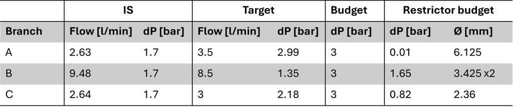
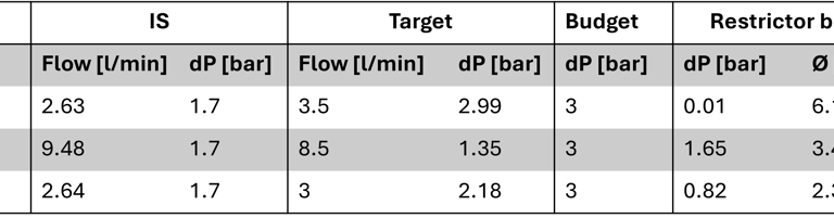
Table 1: Initial and Target State for the Module
In the case above for the branch B two orices were added in order not to have too high water velocities that would increase the risk of erosion, cavitation or even Flow Induced Vibrations (FIV). In the case above we only needed to redistribute the water and there was so violation of any budgets. In the case of budget violations, further design optimisation can be met (like increasing channel sizes) to get back to the already introduced workflow.
Summary
Flow balancing is the disciplined counteraction of water’s natural preference for the path of least resistance. By intentionally increasing resistance in overfed branches, we redistribute coolant to critical paths — often with components considered during the design phase.
Ultimately, flow balancing is not about pushing more water through a system. It is about ensuring the right amount of water flows through the right components — within the limits of the available hydraulic budget.
Counteracting the Nature of Flow
Water is inherently opportunistic. It follows the path of least resistance, instinctively favoring the branch with the lowest pressure drop. In a parallel cooling network, this natural behavior leads to maldistribution: some channels are overfed, while others are starved.
Flow balancing is the deliberate act of counteracting this tendency.
At its essence, flow balancing means adding resistance to branches that receive too much flow in order to redistribute it to those that receive too little—all while staying within a defined pressure drop or pump power budget. It is not about increasing total flow blindly. It is about intelligently shaping resistance so that each critical component receives exactly the coolant it requires.
This directly answers two fundamental thermal management questions:
How can we cool critical components more effectively without redesigning hardware?
• Increase flow where it matters through hydraulic redistribution.
When redistribution alone is insufficient, what hardware interventions are available?
• Introduce calibrated restrictors (e.g., orifices) to intentionally shape the hydraulic network.
Case Study: Parallel Cooling Architecture with Mixed Hydraulic and Thermal Characteristics
For this case study we'll take a look at a module housing three parallel cooled branches with very different components (Image 1 ). The module itself has a baseplate that encorporates the water distribution into the parallel branches::
Branch: two water cooled components connected in series
Branch: cooling plate with meander channel
Branch: cooling helix
Consulting / Simulation / Analysis
Expertise in thermal management and optimization solutions.
chillwave@analytics.com
+4917657864718
© 2025. All rights reserved.