Gas Purging of Modules — Key Considerations, Purge Time Estimation and Eliminating Stagnation Areas (1)
Part 1
PURGING
1/28/20264 min read
Introduction: Why Gas Purging Matters and What to Keep in Mind
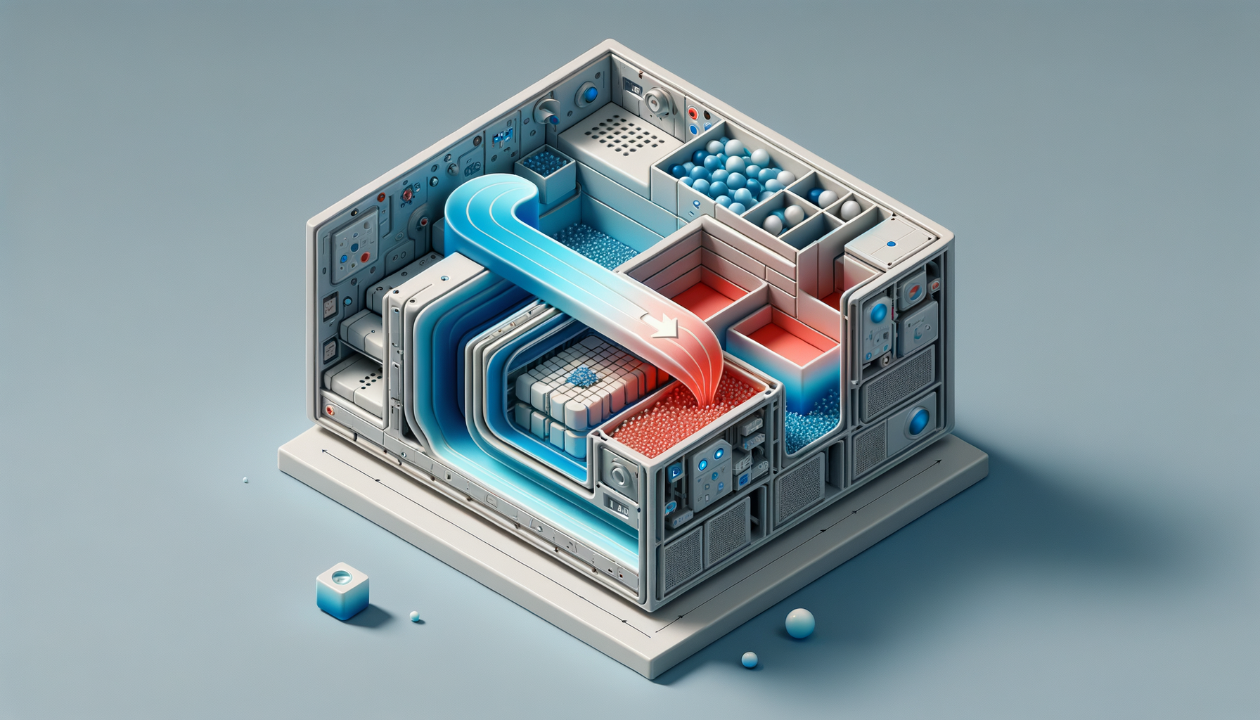
Effective gas purging is essential for ensuring product quality, protecting sensitive components and maintaining process reliability in modules such as laser housings, optical assemblies and process chambers. However, purging is not trivial — it involves balancing flow rates, velocities, geometry and component sensitivity to achieve thorough, fast, and safe gas replacement. In this article the main focus will be how to calculate purging times and what are some good design principles. In a second article some examples and comparisons will take place.
Before diving into purge time calculations and strategies, here are critical factors that motivate and shape purge design:
Cycle time relevance: Purge time must be lower than the overall machine cycles or time needed to achieve stable operating conditions (time constant).
Module complexity: Simple piping systems behave differently from complex optical or electronic modules with many cavities and sensitive parts requiring gentle flow.
Velocity limits: High gas velocities improve purge speed but can damage delicate components or cause contamination. Typical max velocities depend on system e.g., <1 m/s near sensitive optics, higher in ducts.
Component sensitivity: Gas flow direction and velocity relative to critical components matter. Perpendicular jets may damage or disturb; parallel low-velocity flow is preferred. (Highly dependent on system and req)
Thermal effects: Cooling effects (beneficial or detrimental) through purging need to be considered in some occasions, where volumetric flow rates are high or some components have large surface (convective heat transfer coefficient ~20 W/m²K).
1. Estimating Purge Time: Analytical vs. Simulated Approaches
What is Purge time?
Purge time is the duration needed to reduce an undesired gas concentration (e.g., oxygen) inside a module from its initial level to a safe or acceptable target.
Analytical Methods: Simple and Conservative
The most common analytical method assumes the module is perfectly mixed, leading to an exponential decay of contaminant concentration:
$$C(t)=C_0\times e^{-\frac{Q\times t}{V}}$$
Where:
$C(t)$ = Concentration at time $t$
$C_0$ = Initial contaminant concentration
$Q$ = Volumetric flow rate
$V$ = Module's volume
Solving for the purge time $t$ to reach target concentration $C_{\text target}$:
$$t=\frac{V}{Q}\times ln(\frac{C_0}{C_{\text target}})$$
This model is easy to apply and gives a conservative estimate if the module is well-mixed by fans or turbulence.
Alternatively, the turnover or displacement model assumes piston-like flow with minimal mixing, estimating purge time as:
$$t\approx \frac{V}{Q} \times N_{\text turnovers}$$
Typically, 5–10 $turnovers$ are suggested depending on purity requirements.
Simulated Methods: Detailed and Location-Specific
Computational Fluid Dynamics (CFD) simulates transient flow and species transport in the actual module geometry, capturing:
Flow jets and recirculation
Stagnation volumes and dead pockets
Thermal buoyancy effects (if not isothermal study)
Realistic mixing and velocity profiles
CFD helps identify worst-case locations where purge times are longer than bulk averages, guiding design improvements.
Why Do Analytical and CFD Results Differ?
Analytical models assume idealized mixing or displacement and ignore geometry-induced flow complexities. CFD reveals spatial concentration gradients, flow separation and trapped volumes, often showing longer purge times in dead pockets. Thus, analytical times are useful initial guides, but CFD or tracer tests are needed for detailed validation. In a following article we do concentrate on simulative analysis. We mentioned dead pockets, recirculation zones etc... Those could be summarized under the term stagnation areas. Next chapter focuses solely on those.
2. Stagnation Areas: Identification and How to Address Them
Why Stagnation Areas Matter
Stagnation/ Recirculation Areas trap contaminants, prolonging purge times and risking component damage or process failure even if bulk concentrations appear acceptable.
Common Locations of Stagnation
Corners and cavities behind brackets/ walls/ shelves
Entrapped volumes in manifolds or housings
Areas shielded from direct flow by components
Regions downstream of flow separations causing recirculation
Identifying Stagnation
CFD concentration maps and probe monitoring
Streamlines visualisations
etc.
Addressing Stagnation
As everything else in engineering addressing stagnation areas is somewhat a trade-off problem. First of all a decision has to be made on when the system is good enough - that is very specific question, tightly related to the system and it's boundary conditions. Second the decision has to be met how to get to the desired state and here the discussion will go into that direction. There are mainly three ways how to appoach that problem. The first is to introduce some design changes to the module and second is to introduce oprational adjustments and of course the hybrid approach, where a combination of both can be used.
Design Changes
Often those changes need to be considered with respect to volume claims inside and / or outside of the module.The additional development, infrastructure costs and leakage risk should not be overlooked.
Strategic Inlet / Outlet Placement:
Place inlet and outlet diagonally to create a displacement sweep.
For heavier gases (argon) inlet lower than exhaust or for lighter gases (helium)- reverse. Buoyancy is a friend! :)
Avoid placing outlets near inlets. Short-circuit prevention.
Multiple Inlets/ Outlets:
Pros: Improved flow uniformity, reduced dead zones and accelerated purging
Cons: Added plumbing complexity, cost and potential leak points; Required flow balancing
Flow Guides/ Obstructions:
Add vents or bleed holes to trapped cavities
Install flow guides, perforated plates, or plenums to distribute flow evenly
Use internal fans or mixers if compatible with process
That is about it for the theorical side of purging. In second part of the article some comparisons and real examples will be presented alongsinde with few of the approaches for handling stagnation areas, which will be discusseded in greater detail.
Take a look at the second article:
Gas Purging of Modules — Key Considerations, Purge Time Estimation and Eliminating Stagnation Areas (2)
Consulting / Simulation / Analysis
Expertise in thermal management and optimization solutions.
chillwave@analytics.com
+4917657864718
© 2025. All rights reserved.